
The gShield is awesome. You can build a 3 axis DIY CNC Controller for less than $80!
This post will walk you through the step-by-step process of setting up your own DIY CNC Controller. If you want to dive right in download the Quick Start Guide here. If you get stuck check back here to find the detailed setup instructions. Happy making!
Introduction
I love the gShield from Synthetos! No, they are not paying me to say that. As a die hard gear head, electronics intimidate me. I cannot say why, they just seem like a mystery. Mechanical stuff I get. I see how it works. I can’t see the electrons in the printed circuit board or the 1s and 0s in the software.
Enter the Arduino. This created a completely new world for me. It’s nearly indestructible. I mean I have been trying to let the manufacturers smoke out of the device for years now. (The long running joke is that manufacturers pack smoke in electrical components that is let out when someone screws up and they fry the chip as demonstrated by the smoke coming out.)The combination of Arduino with grblShield allowed me to create a DIY CNC Controller for less than $80! That’s crazy! And the best part is, I am not tied to a boat anchor of a PC with a parallel port typically required to run stepper motor drivers.
Correct me if I am wrong but I do not know of any industrial CNC controller that uses anything other than a parallel port. I mean come on! I don’t know of any printers that still use a parallel port. Please, someone put it out of its misery. Ok, my rant is done.
One huge advantage of the grblShield with the Arduino is the ability to use a regular old USB connection. Welcome to the 21st century. I know don’t fall out of your chairs. My harbor fright mini mill isn’t all that big. I really didn’t want the controller to be bigger than the mill. If I was to use a parallel port that means finding an old PC with a stable version of windows and probably using Mach3. I didn’t want to mess with that.
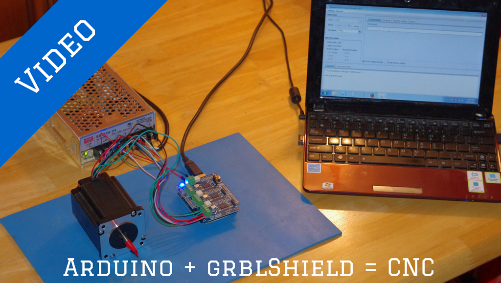
Click here to watch the video on YouTube.
The following is a step by step guide to create a 3 axis DIY CNC Controller. Let’s walk through the setup starting with a list of hardware you will need followed by a list of tools that will make the job easier.
Note several of the links below are affiliate links. If you choose to purchase through one of the links below, I will earn a small commission which helps maintain this site. If not, that is fine too. Either way your the price you pay does not change. You can read more about my affiliate disclosure here.
Required Hardware…
- Arduino UNO or clone I am partial to the SparkFun RedBoard – Programmed with Arduino
- gShield available here from Synthetos
- Power supply (12 or 24 volt) Mean Well SE-200-24 Single Output Switching Power Supply 24V 8.8A I used a 24 volt supply because the grblShield is rated for 30 volts and 2.5 amps per driver. I want to push as much power as I can recall P = IV where P = power, I = current and V = volts. If I say double the voltage from 12 to 24, I double the power if the current I is held constant.
12 volt example – 2.5 amps x 12 volts = 30 watts
24 volt example – 2.5 amps x 24 volts = 60 watts
Also, most 24 volt power supplies have a voltage adjustment screw which will let me get about 28 volts and drives the power per stepper motor up even more.
- Stepper motor(s) NEMA23 425oz/in 2.8A Stepper Motor ¼” Dual shaft
- PC or laptop with USB port ASUS Netbook
- Hookup wire (14 or 16 gauge stranded) 18 AWG 4 Conductor Shielded Cable (25ft.)
- Plug end for the power supply AC Power Cord 6 Ft 18 AWG 3 Prong
You will also want to have the following tools on hand…
- Multimeter – I have fluke meter that I picked up on sale a few years back for other stuff. They work really well but you can get a nice meter for 10 -20 bucks.
- Small screwdriver
- Soldering Iron – Depending on the age of your Arduino, you may need to move a jumper
- Wire cutters
- Wire strippers
- X-acto knife or equivalent
Get the Quick Start Guide Here
Overview
- Download and install the grbl software on your Arduino
- Download and install the Universal Gcode sender on your PC
- Wire your power supply (confirm polarity of power supply and set to 110 VAC)
- Connect the power supply to the grblShield and test
- Connect the grblShield to your Arduino
- Test the connection
- Wire your stepper motor to the grblShield
- Test the stepper motor
Step 1 – Download and install the grbl software on your Arduino
The following method uses the Arduino IDE (Integrated Development Environment) to load the grbl software to the Arduino. The process is very similar to loading a “sketch” to your Arduino. If you are not familiar with loading software to the Arduino or do not have the latest Arduino software on your PC then take a few minutes to load the latest IDE available by clicking here.
- Go to the grbl home page on GitHub by clicking here.
- Click on the “Download ZIP” button on the right side of the screen. See the picture below.
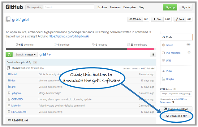
A screen shot of the GitHub page for the grbl software.
- Save the file to your computer and unzip to create a grbl-master folder. I placed the grbl-master folder in my Arduino folder. The file structure will look something like …/Arduino/grbl-master (Note default Arduino installation path is “C:\Program Files (x86)\Arduino”)
- Open the Arduino IDE and confirm you have at least version 1.8.10 (You can check which version of the Arduino IDE you have by going to the “Help” drop down menu and then selecting “About Arduino”)
- Next, you need to add the GRBL library to the Arduino IDE. Click the “Sketch” menu then select “Include Library” then choose “Add .ZIP Library“
- Locate the “Grbl” folder downloaded from the GRBL github site (Note, you will need to click through the “Grbl-Master” folder to get to the “Grbl” folder. If not, you will get an error.)
- Click the “File” drop down menu then “Examples” then “grbl” (this will probably be all the way at the bottom of the menu) and finally “grblUpload”. This will open the GRBL sketch that needs to be uploaded to the Arduino.
- Connect your Arduino & select the com port used by your Arduino by using the “Tools” drop down menu then “Port”.
- Upload the GRBL sketch to your Arduino – Be sure to select the com port your Arduino is using
Note when I wrote this post, the latest Arduino version was 1.61
Step 2 – Download and install the Gcode sender on your PC
This software gets loaded to your PC and will send the Gcode to the Arduino. The UniversalGcodeSender is a Java based software and will require a least Java 7 be installed on your machine. You can check to see if you have Java installed on your computer by going here.
Click on the “Activate Java” button in the center of the screen to detect if Java is installed on your machine.
To download the latest Java version go here. Be sure to pay attention during the installation. There is a check box that is set to change your search engine and home page to “Yahoo.” If you don’t want that to happen make sure you uncheck the box. See the screen capture below.
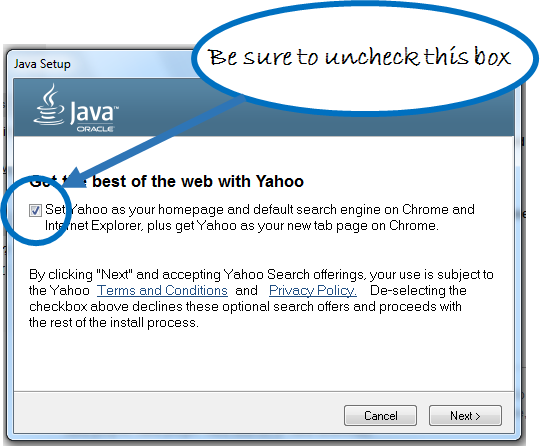
Be sure to uncheck this box during the Java install otherwise your default search engine will be set to Yahoo.
Now onto installing the Universal Gcode Sender…
- Go to the Universal gCode Sender home page on GitHub by clicking here.
- Scroll down the page to the “Downloads” section. I like to work from the latest stable build in the case
1.0.81.0.9
- Click on the version number you wish to download.
- Unzip the folder and place it in your “Program Files” folder.
- Finally, create a desktop shortcut of the UniversalGcodeSender.jar extension by right clicking on the file and selecting “send to” then “desktop (create shortcut)”.
- Double click the UniversalGcodeSender.jar
That’s it! The software bit is finished. Now let’s put some hardware together. You are well on your way to getting your DIY CNC Controller running.
Step 3 – Wire your power supply (confirm polarity and set to 110 VAC)
WARNING – Use extreme caution here. You are dealing with 115 volts alternating current (household power) which can be very dangerous. If you don’t know what you are doing find a licensed professional to help you.
- Find the input power selector switch on your power supply and set it to match the AC line voltage you plan to use. This is really important. If the switch is not set correctly, you will destroy the power supply. In my case I set the switch to “115 VAC”. See the picture below.
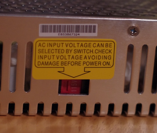
AC voltage input selector switch located on the side of the power supply.
- Locate a donor power cord for your power supply. I used an old PC power cord and cutoff the female end.
- Remove approximately 1.5” (inch) of the outer cable sheathing. Be careful not to nick the conductors inside the cable. I used a sharp Xacto knife with a few light passes. I don’t cut all the way through. Instead, I take then end and split the cable sheathing along my cut line.
- Strip back the insulation approximately 1/4” on each of the green, black and white wires.
- Next, connect the green wire (ground) to the ground terminal labeled “⏚” on the back of the power supply.
- Connect the white wire (neutral) to the terminal labeled “N”
- Finally connect the black wire (line) to the terminal labeled “L”
- Double check all of your connections and make sure the DC voltage terminals are clear.
- Plug in the power supply and confirm its working. You will see a green LED light up near the terminals. Do not touch any of the terminals!
Click this link for the MeanWell SE-200 datasheet to learn about the power supply I am using. I purchased mine from Mouser for a total of $46.10 including tax and shipping. I know you can get cheaper power supplies but I have always had good luck with MeanWell products.
Step 4 – Connect the power supply to the grblShield and test
Now that you have your power supply all wired up, it’s time to connect it to the grblShield.
CAUTION – the grblShield does not have reverse polarity protection. If you hookup the supply voltage backwards, you will destroy your grblShield and need to send it back for a replacement.
- Using your multimeter confirm the output voltage and polarity of your power supply. You should see approximately 24 volts.
- Unplug the power supply.
- Connect the V+ terminal on the power supply to the Vmot screw terminal on the grblShield. I used 16 AWG stranded wire.
- Connect the V- terminal on the power supply to the GND screw terminal on the grblShield.
- Confirm you have the wires between the power supply and grblShield connected properly. I don’t want you to be slowed down by having to send your grblShield back to Synthetos.
- Plug in the power supply and confirm your grblShield is working. You will see a blue LED light up near the screw terminals. Again, do not touch any of the terminals!
- Unplug the power supply.
Click here for more details about getting started with the grblShield.
Step 5 – Connect the grblShield to your Arduino
If you have the latest version of the Arduino UNO rev 3 (R3) you can simple plug the Arduino into the grblShield. The Arduino R3 version has 8 pin header socket as the power. If you have an R3 just skip to Step 6.
However, if you are like me and you have an older Arduino, then you will need to make a quick mod to the grblShield that involves cutting a trace on the PCB and adding a jumper. It sounds daunting but it takes just a few minutes. The following process walks through the modifications required if you have an older Arduino.
- Disconnect all power from the grblShield.
- Cut the far left trace in the J11 power jumper section using a sharp x-acto knife. See the image below. The power jumper section is a 2×3 arrangement of plated through holes in the PCB below the Z axis stepper motor drive.
- Add a jumper wire to the far right pair of plated through holes in the J11 power jumper section. These are closest to the J5 and J6 markings on the PCB. I used a scrap piece of wire cut from a resistor and soldered the jumper in place.
Click here for additional logic power settings on the grblShield.
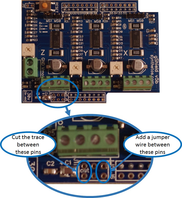
Moving the grblShield power jumper to accommodate older Arduinos.
Step 6 – Test the connection
Now it’s time to see if your PC, Arduino and grblShield are all playing nicely together.
- Connect the USB cable to your Arduino and PC
- Plug in the power supply for your grblShield
- Power on your PC and launch the Universal gCode Sender by clicking on the desktop shortcut
- Set the communication baud rate in the Universal gCode Sender to 115200. (Note if you are using grbl version v0.8 or lower set the baud rate to 9600.) See the picture below.
- Next select the COM port used to connect to your Arduino. if you do not know which one is, try the first COM port listed.
- Press the “Open” button next to the Baud rate selection box.
- If all systems are go then you will see a welcome message in the console window “grbl v0.9 [‘$’ for help].”
- If you received the welcome message, unplug your power supply and disconnect your Arduino from the PC.
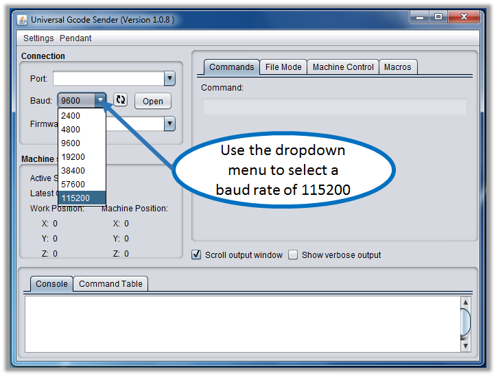
Select the baud rate using the dropdown menu. For grbl version v0.9 use 115200.
Step 7 – Wire your stepper motors
The following process is for the 425 oz-in stepper motors available from Automation Technologies Inc.
These are 8 wire stepper motors. But wait the grblShield only has 4 connection points for each motor. These stepper motors have 4 coils. We need to configure these coils in such a way that we end up with 4 connection points. There is a bunch of data that describes the optimal way to wire a stepper motor. I chose the Bipolar (parallel) configuration. This will allow me to get the most out of these motors. In this configuration the motors will draw 2.8 amps (just slightly above the 2.5 rating of the grblShield) but based on the information from Synthetos, these work really well.
The motors have the following 8 wire leads each color coded:
Blue/White, Blue, Red/White, Red, Green/White, Green, Black/White, Black
You can use the data sheet to confirm the following wiring pattern.
A+ = Blue/White & Red/White
A – = Blue & Red
B+ = Green/White & Black/White
B- = Green & Black
I twisted the wire pairs together before installing them in the grblShield. The terminal clamps use tiny flat head screws and you will need a nice small screwdriver.
- Ensure all power is disconnected between the grblShield and Arduino. This includes the USB cable that connects the PC to the Arduino. Make sure this is removed before connecting the stepper motors.
- Connect the wire pairs to the X axis stepper motor terminals in the order listed above. See the picture below
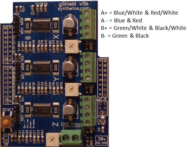
Stepper motor wiring order.
Step 8 – Test the stepper motor
Now let’s bring it all together and make some noise!
- Find the current limit potentiometer on the grblShield for the axis you are using for your testing. I used the x axis.
- Gently turn the potentiometer counter clockwise until it stops. Forcing the potentiometers beyond the stop will make the axis inoperable.
- Power on your PC and launch the Universal gCode Sender by clicking on the desktop shortcut.
- Plug in the power supply for your grblShield.
- Next connect the USB cable to your Arduino and PC .
- Confirm your PC is talking to the grblShield by checking for the welcome message in the console window “grbl v0.9 [‘$’ for help].”
- Next type “G0 X1000” in the command window. This is a g-code command that tells the x axis to move 1000 mm from its current position. (The grblShield defaults to mm but this can be changes to inches if you are more comfortable in that unit system.)
- Gently turn the potentiometer clockwise until the motor begins to turn. Keep going until the motor runs smoothly. Note you will likely need to repeat this step one the stepper motors are installed in the machine.
- Send a few more g-code commands or play around with the buttons under the “Machine Control” tab.
The good folks at Synthetos have a nice getting started page for the grblShield here.
Final Thoughts
Wow, that’s a bunch of information to digest. If you have any questions or get stuck along the way feel free to e-mail me Tim@diymachining.com
Don’t forget to download the Quick Start Guide here. If you are a visual person, this is more your style.
Good luck with your project. I would love to hear what you are building with your DIY CNC Controller. Leave a quick note in the comments below.
Thanks for reading. Until next time… Tim
Hi Tim I have been searching for a site like yours. I have one question right now I tied to get universal gcode sender but will not open in windows 10. No time now but will talk to you later. PS.your site is fantastic nice and plain explanations.
Mike,
Thank you for the kind words. I am not sure if Universal gcode sender will work on Windows 10. When you unzip the zip folder, do you see a .jar file? If not, you likely need to install Java. You can go here to test if your machine has Java installed https://java.com/en/download/installed.jsp?detect=jre&try=1
Also, have you tried the latest version of Universal gcode sender which is 1.0.9? I need to update my post to reference this new version.
Hi Tim you say grbl shield defaults to mm how do you change to inches sorry for being a pain but you don’t find out things if you don’t ask right. Thanks again. Mike.
Mike,
If you are using the Universal Gcode Sender, type $$ into the “command” box. There is a screen shot here http://www.diymachining.com/grbl-settings-101-a-how-to-guide/
This will display the current GRBL settings. You should see a list like this https://github.com/grbl/grbl/wiki/Configuring-Grbl-v0.9
In the “command” box type $13=1. This will tell GRBL to report machine position in inches.
Great work
Thank you Lanton!
hi chief
is there a way to wire a gaming controller to the arduino to make it move the cnc, I want to do this so I can stand away from the computer when setting up my work pieces to find its starting point. I am just using the arduino uno and currently move it with the inventables soft wear and have to walk back and forward to check perfect zero
James – I appreciate the comment. It’s something I am considering as well. The best info I found is here on the ShapeOko Wiki. http://www.shapeoko.com/wiki/index.php/Pendant
There are a few links in the wiki section to specific forum post where people explain how the setup is made. The solutions I have seen connect the game controller to the computer and use a 3rd party software to map the buttons on the game controller to functions in the gcode parser. Let me know how your solution works. Walking back and forth between the machine and the controller gets annoying when you are setting zeros.
First, thank you for doing this. Here’s a few notes and steps that differed on my install from the written directions.
Windows 7, Arduino Uno R3 with V3 GShield
Step 1.3
Arduino’s default install is C:\Program Files (x86)\Arduino
Step 1.6
The commands in Arduino 1.7.10 are now Select the “Sketch” drop down menu then “Import Library” then scroll to the bottom of the drop down menu. “GRBL” is located on the bottom.
Select the “Tools” drop down menu, “Port”, and your specific port. I used COM3.
Step 6.1
Swap step 6.1 and 6.3
Step 6.1 and 6.3 did not work for me in the original order. I connected the USB cable to the Arduino and computer before opening the Universal Gcode Sender. They worked great when swapped.
Step 6.5
“grbl v0.9 [‘$’ for help].” did not appear on my screen. My solution:
Set Port to “Com3”.
Select Baud 115200 and press Open.
Select the “Machine Control” tab.
All systems are go if all buttons on the tab are functional.
Some Guy – Thank you for the updates! I will review and make the changes.
Hi Tim excellent article thank you
Now for the questions
Do you really need a shield ? I have 3 drivers for my motors.
What is the purpose of the shield?
I have Mach3 demo on my computer an uno three stepper motors with a drive for each and a power supply. If I finally get grbl on my arduino ( struggling for some reason with this)
Would I need any thing else ?
Paul – Thank you, I appreciate the feedback. The short answer is no, you do not need anything else. Some folks like the shield because it makes the wiring part a little easier. In my case, I am using a gShield which has stepper drivers built into the shield. How I can help with getting GRBL loaded onto your Arduino?
What is best to use as power a 12V psu or a 24V PSU?
Allan – I prefer the 24V power supply. Using the higher voltage helps keep the current at lower levels for a given power output compared to a 12V supply.
The data sheet for the motor specifies 9 V max, so you are turning down the potentiometer for the current limit to achieve this. It would work the same with a 12 V supply.
Hi Tim,
Just want to thank you for an informative site. I had read a bunch of information and couldn’t really tighten them together. Your effort was very helpful.
Emanuel
Emanuel – I appreciate the feedback. I created the site for that very reason. I felt like the information was scattered in a variety of places.
Hi Tim, Thank you for providing a tutorial on how to find and load the necessary software to set up an Arduino for use with a gShield. Your’s is the first detailed “how to” that I’ve come across after a couple of months poking around for some guidance. The last comment posted was from Paul (10/4/16) who had drivers for his steppers and asked if the gsheild was really needed, to which you answered “no.” What I hope to learn is where I can pull off the step and direction pulses from either the Arduino alone or the Arduino in conjunction with a gshield? I suppose it would be useful to know whether the pulse signals were sinking or sourcing.
Terry – Good question, I would check out this page https://github.com/grbl/grbl/wiki/Connecting-Grbl
Hi Tim,
Great article, very helpful!
I am building a 2 axis cnc-like gantry with a servo gripper. I would like to use only one Arduino, but it looks like the grblshield would not permit this. Is the solution to use a driver for each stepper, then use something like this https://github.com/robottini/grbl-servo to control both the steppers and the servo together?
Very new to this whole topic,
Thanks!
Isaac – Great question. I am not familiar with nor have I used the Robottini stuff. Are you using a hobby servo? I would love to hear how the project turns out.
Tim –There are many utube vedios telling how to set up the arduino/shield,but yours is by far the easiest to follow. Thanks
Howard – I appreciate the feedback. Glad you find the video helpful.
I have arduino CNC Shield v3.0 and I am hooking my end stops, which wires go to the two pins ,black and white, on the right side of the shield for X+ and – and Y + and –
the end stop wires are red, black and green.
Thank you for the help.Bruce
Bruce – Good question, I will need a little more information about your end stop switches. Will you reply with a link to the product page? You can also email me at Tim@DIYMachining.com You can also check out the following page which details how to install limit switches. https://www.zyltech.com/cncs.html I suspect, the three wires from your end stop switches are COM (common), NO (normally open) and NC (normally closed). If you want to run your end stops as normally open, then just connect the green and black to the X+ and X-.
very informative content
Hi Tim, Very impressive article. I’m Maarten from the netherlands and i bought a CNC 3018 DIY Machine from China. The hardware seems ok, but i’m concerned about the PCB board. A new one is shipped from china already..
CNC3018-ER11-GRBL-control-Diy-CNC-machine-3-Axis-pcb-Milling-machine-Wood-Router-laser-engraving
Is it possible to replace the whole existing PCB board for an Arduino and GRBLshield?
Regards,
Maarten
https://nl.aliexpress.com/item/CNC-3018-laser-options-diy-mini-cnc-engraving-machine-Pcb-Milling-Machine-Wood-Carving-machine-cnc/32805289008.html
Hi Maarten, That’s a really good question. The short answer is yes, you can replace the motion control functions of your machine with an Arduino + grblShield combination. This will drive the steppers in all 3 axis. However, you will need to sort our what to do with the spindle motor. It was not clear to me from the link if the spindle motor control functions are also part of the original PCB. The gShield will allow you to control a spindle. Note these are control signals only and would require an external motor controller. If that’s not clear, feel free to send me an email Tim@DIYMachining.com and we can setup a Skype call to discuss further.
Thanks for all of the info you posted. I’m not sure I understand all of the software needed. Can this work for say, Mach 3 or 4? Maybe some other software?
Hi Al, GRBL can be made to work with Mach3 but it looks messy. I have never done it. What I really like about GRBL is you don’t need a parallel port and the software is open source. I use Fusion360 to create my CAD & CAM files as well as produce (post process) gcode. Fusion has a native GRBL post processor. From there I copy the gcode .nc files from my desktop to my Netbook connected to my CNC mill. The Netbook runs Universal gCode Sender (UGS) to stream the gcode to the Arduion. The GRBL software is loaded on the Arduino. Does that help? If not, feel free to email me at Tim@diymachining.com
hi body i have
Question how install limit switch for arduino and shiled cnc
and how tuning limit switch and how calibrated program ugs for cnc
Hi Mateom, I replied to your comment on the G-code example post. I recommend you take a look at the following for a guide on installing limit switches. https://github.com/gnea/grbl/wiki/Wiring-Limit-Switches
Great Site!…. As stated by another visitor, this is exactly what I have been looking for. I have a couple of questions, Is there some place on the site I should register, or is this comment section open and free to post to? Should I simply post my questions here? ( The Irony of me asking these questions is not out on me…lol ) I am attempting a few projects / builds, as well as attempting to convert a few of my machines to Arduino based control. I have a home Built CNC that I ave a Gecko Drive running on…. but being a MAC guy I would like to use something other than MACH 3 and serial ports on the old PC’s I have laying around. I am also building a smaller ‘light Duty” CNC that I want to use a MAKERBASE TFT 3.2 and V1.5 Drive board to control . Lastly I have 2 Laser Engravers I would like to swap out the existing Control boards on. So…. those are my goals … am going t start ne at a time… with the first goal being setting up My Arduino 2560 with Shield & drivers + LCD Screen for CNC Use. Please let me know the protocol for posting on here with my projects / questions.
Geat work here Tim, I appreciate your Time and efforts, as I am sure we all do!
Mack
Hi Mack – Thank you for the kind words. Feel free to post comments or e-mail me directly at Tim@diymachining.com The comments sometimes lag as I have to approve all of them to filter the spam.
Hi Tim,
you are driving 2.8 A Stepper with 2.5 A max driver. I’m little bit confused how this is possible without taking the driver to the “edge”. Am I missing something ?
Robert
Hi Robert – You are correct, I am driving a 2.8 Amp stepper motor with the gShield v5 which has the 2.5 Amp stepper drivers. I have the current potentiometer dialed back just a bit for each axis. I also fan cool the drivers to keep them at a nominal operating temp. I have experienced several crashes where I have stalled the stepper motor mechanically without any damage to the electronics. My setup is going on 4 years old without any issues.
Can you tell me what format the gcode should be exported as for gcode sender to use? I tried various ATC.nc but either small,a square instead of circle or errors (70,71 and others).
Hi Jeff, you will want to use a GRBL compatible post processor. Universal Gcode Sender (UGS) just sends the gcode from the file to GRBL. What CAM software are you using?
I have a camtool cnc v3.3 and can’t get the correct board setting to send grbl. where can I find the correct board setting?
Hi Kim, ah that sounds frustrating. IF I understand your question correctly, you are having trouble connecting your Arduino to the Arduino IDE on your PC to load GRBL onto the Arduino. The CamTool CNC V3.3 looks like an Arduino Uno clone. I would try selecting Arduino Uno as the board type in the Arduino IDE. Click the “Tools” menu then select “Board:” this launches the board manager and you can select “Arduino/Genuino Uno” If that doesn’t work, you might try a few of the other board options to see if you can connect. If not, you might have a bad board or one with a counterfeit USB chip. If you are still having issues feel free to email me at Tim@DiyMachining.com
ok great site ok just bought a workbee 750mm x 750mm cnc routing machine china knock off came with no wiring diagrams or mechanical diagrams got it put together with the help of the www the stepper motors are yuyonc mod.yh57bygh56 401a the wires are black,green,red,blue i know about pairing the wires the x axis has 2 motors need to no which wires in order for the cnc shield and how to change the rotation of 1 of the motor in the x axis it look like wiring the gshield mite be easier my shield has the motor drive on the board i hope you can understand my need for help very very new at this stuff thanz
Hi Victor, I replied to your email. Generally, it’s best to use one driver per stepper motor. You can split the step and direction signals from the Arduino and connect two different drivers for dual motors on say the X axis.
I need GRBL software with better spindle speed control. I’m hoping this one will do the trick.
Terry, thanks for the comment. When you say you need “GRBL software with better spindle control,” are you talking about the software that runs on your PC to stream the gcode to the Arduino running GRBL? In this case, I use Universal Gcode Sender. I am very happy with it for my application. IN the interest of full transparency, I do not use GRBL or Universal Gcode Sender to control the spindle on my CNC mill. I do that manually. I start the spindle and then send the gcode file.
I have problem motor A4988 in arduino sheild no move pleas help me and thanks
Hi Mostafa, will you send me a few more details? Are you having trouble with just one motor are is this a problem with all the motors?
Tim, this is a great site and thanks for sharing. I am new to this but plan to build a CNC router very soon. I didn’t realize you could wire the motors without drivers because all of the information I have been reading has been on a GShield at the Amazon site. Their GShield requires motor drivers but they don’t carry the one you discuss. Do you know the differences? I plan to order from the site you provide but I like to understand as much as I can and I am very new. Is the V5 still the version you would recommend? Anything I need to look out for when ordering my Ardriuno? Thanks again, I will use your information for my machine.
Matthew, glad you found the site helpful. To clarify, all stepper motors require drivers to run them. In the case of the gShield, the stepper drivers are integrated into the shield. For other generic “CNC” shields, you purchase the drivers separately. I would use the gShield V5 (grblShield) again in a heart beat if you only need 3 Axis control. If you want more axis, check out the TinyG also by Synthetos. https://synthetos.com/project/tinyg The TinyG will do up to 6 axis.
Tim,
I wanted to thank you again for making this information available and so easy to understand. I have purchased some small components to play with and I have been able to make it work and understand more about the electronics and software. I have also started building the frame for my real machine. Quick question, I found some NEMA 23 motors I like that require 2.8 amps and I read the gShield can handle 2.5 amps. I noticed you used 2.8A motors as well. Do you adjust the motor driver to 2.8 or just adjust it as high as it will go? I am seeking budget components as much as possible. My machine uses ball screws and is has about a 36″ x 36″ working area.
Matthew, great question. Yes, I have been using 2.8 Amp NEMA23 steppers for more than 5 years now without any issues. I set the current limiting potentiometers (pot) by setting the highest rapid speed I wanted and then ensuring the driver pot position could support the required current draw. Mine are not all set at the maximum but are set at the higher end of the available range.